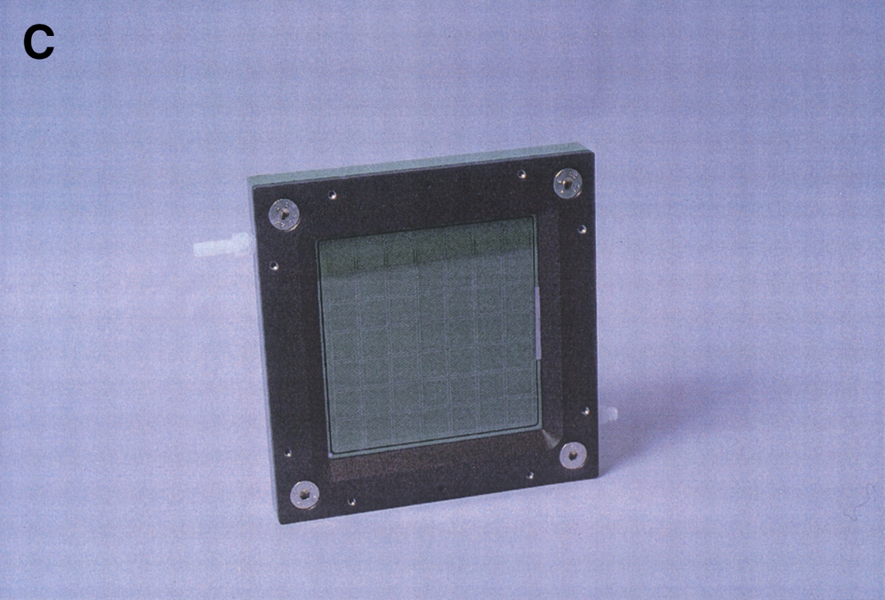
The hybridization chamber/flow cell. (A) Components of the hybridization chamber. The glass wafer is shown in the front right, with individual arrays visible as squares. The size of the wafer is 12.5 cm × 12.5 cm. The grid plate and seal, which provide separation between the arrays during hybridizations, are in thefront left and middle, respectively. The seal fits into a groove machined into the grid plate. The central frame is in theback left and the outer frame to which the support plate has already been attached is in the back right. (B) Assembled hybridization chamber. The central frame is shown from the direction facing downward in A. The wafer is clamped between the central and outer frames against an O-ring sitting in a groove on the central frame. The grid plate with the seal is attached to the central frame, pressing the seal against the wafer. (C) Flow cell. The grid plate and seal have been replaced by a solid plate with an O-ring around its periphery to prevent leakage and the back support plate has been removed. Teflon adapters attached to the ports in the central frame can be seen in white at the top,left and bottom right corners of the flow cell.